In my last blog, I described the analog audio output using the Arduino Audio Tools library: The STM32H743VIT6 microcontroller is quite powerful but we only have max 2 DAC pins available!
This restriction falls when we use PWM: We use a PWM frequency above the hearing range (30khz) and modulate the PWM Duty Cycle with the audio signal.
Compared to the demo pwm sine example, I increased the sample rate to 44100 and the channels to 2 and I defined the two output pins.
#include "AudioTools.h"

AudioInfo info(44100, 2, 16);
SineWaveGenerator<int16_t> sineWave(32000);
GeneratedSoundStream<int16_t> sound(sineWave);
PWMAudioOutput pwm;
StreamCopy copier(pwm, sound);
int pins[] = {PA1, PA5};


void setup() {
  Serial.begin(115200);
  AudioLogger::instance().begin(Serial, AudioLogger::Warning);

  // setup sine wave
  sineWave.begin(info, N_B4);

  // setup PWM output
  auto config = pwm.defaultConfig();
  config.copyFrom(info);
  config.setPins(pins);
  pwm.begin(config);
}

void loop(){
  copier.copy();
}
Here is result from an oszilloscope:
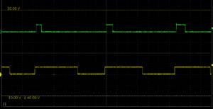
It seems that the output signal between the different channels are not quite in synch but apart from this, it seems to work perfectly.
To turn this into a proper sine wave on the oscilloscope, we would need to add a low pass filter. But you can connect some earphones directly, because your ears will act as low pass filter since humans can only hear up to 17’000hz and this decreases when we get older.

0 Comments